Instruction Manual BARRIQUAN [ BRQ-TX01 ]

Instruction Manual (Web Manual) for BARRIQUAN BRQ-TX01, a tool holder for deburring with floating mechanism.
|
Contents 3. How to Attach/ Remove the Tool 4. Rotation Speed and Feed Speed 5. Offset Amount and Compression Amount |
|---|
1. Precautions
2. Tool Selection
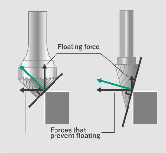
Cutter: 90° angle at the tip is recommended
A conical carbide rotary bar with a 90° tip opening angle is recommended.
Use of sharp-edged cutters will shorten the life of the tool due to forces that prevent it from floating.
Cutter: The more blades, the better
A cutter with a large number of blades is preferable for float processing.
Fewer blades will deteriorate the finished surface.
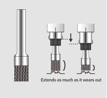
Brushes: Bristles should have cutting power at the tips
If the burr thickness is less than 0.15 mm, it can be deburred using a brush.
The floating mechanism allows the tip to extend as much as it wears, enabling stable deburring.
3. How to Attach/Remove the Tool
1. Remove the Floater from the Shank.
2. Attach the tip tool to the Floater.
(Remove the tip tool from the Floater.)

- Use a flare nut wrench (3-point support) to screw in the collet.
- Using a spanner (2-point support) to screw in the collet causes deflection of the tool and affects the finish of the working surface.
- If brushes are used, they should be φ20 or smaller.
- Attach the tip tool to a φ6 collet (spanner size 10, 13).
- The tightening torque of the collet is 6 N・m.
4. Rotation Speed and Feed Speed
Use a rotational speed in the range of 2,000 to 12,000 min-1.
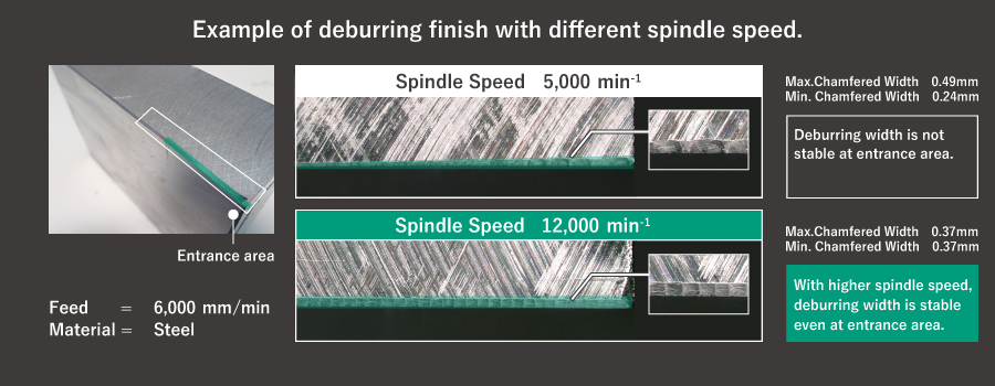
Although the entrance area is one of the most difficult areas with float deburring, you can obtain stable deburring surface with high spindle speed.
High-speed, high-feed processing shortens cutting time
The guideline ratio of spindle speed (min-1) and feed speed (mm/min) is approx. 1 : 0.3 - 0.6.
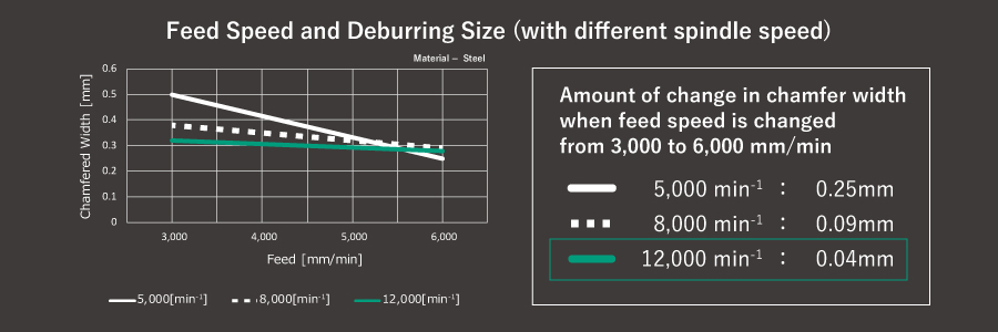
Higher spindle speed enables higher feed speed.
Smaller deburring cuts can be obtained at higher spindle speeds.
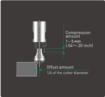
5. Offset Amount and Compression Amount
Set the offset amount to 1/4 of the cutter diameter as a guide.
Set the compression amount from 1 to 5 mm as a guide.
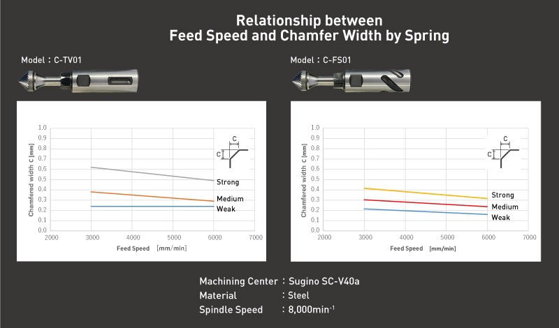
6. Approximate processing conditions
The approximate processing conditions will vary depending on the workpiece material and the Floater used.
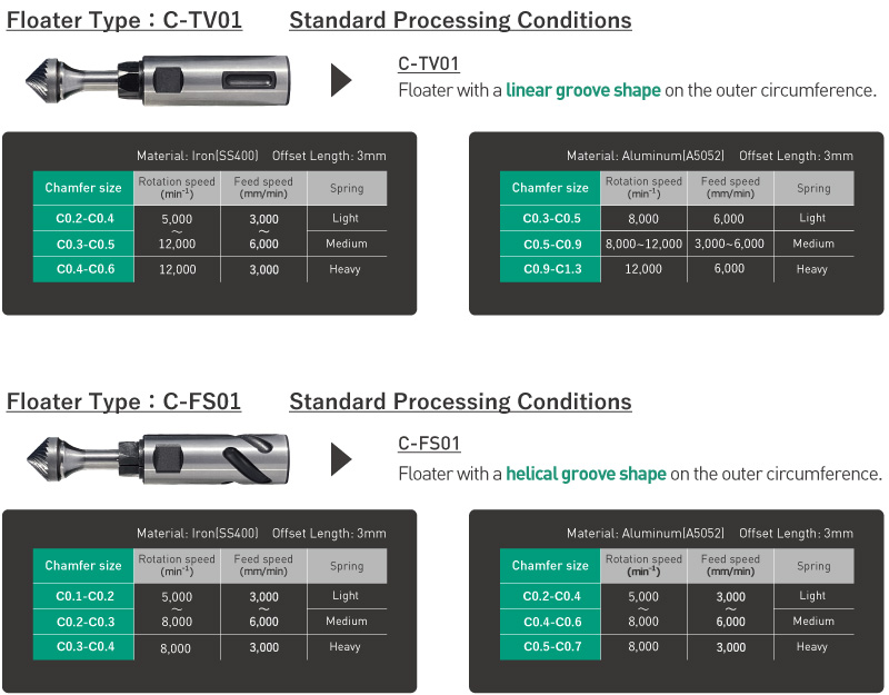
Use the above table as a guide for processing conditions.
C-FS01 has a smaller chamfer width than the C-TV01.
Soft materials tend to have large chamfer widths.
If runout occurs when installing the tool, the chamfer width will increase.
Set the tip runout accuracy of 0.01 mm/rev or less when processing smaller chamfer widths.
7. Setting the Pressure
First, use the Spring (medium) assembled in the main body for processing.
If you want to increase the chamfer, replace the Spring (heavy).
If you want to make the chamfer smaller, replace the Spring (light).
The Rear Cap can be attached and removed by hand, and no disassembly tool is required to replace the Spring.
(*The structure is designed to prevent loosening even when used at high speed rotation.)
Since the chamfer width varies depending on the strength of the Spring, select an appropriate Spring for use.
9. Maintenance
(1) Replacement of Tip Tool
Replace the tip tool with a new one when the blade is chipped or cutting power is significantly reduced.
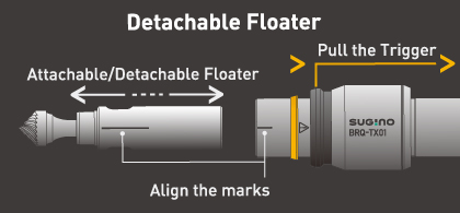
(2) Maintenance/Replacement of Floater
You can pull the Trigger and change the Floater in 3 seconds.
No need to waste your time for tool changes.
No tool is required for daily maintenance.
Daily maintenance will extend lifetime of BARRIQUAN.
Replace the Floater when scratches or dents occur on the outer surface of the Floater.

- Be careful to avoid deformation of the two-sided portion of the Floater when attaching/removing the tool. If the Floater is deformed, the extending/contracting mechanism may not operate properly.
(3)Replacement of Spring
Replace the Spring after 100,000 cycles.
Coil springs lose tention after prolonged use.
-End-